We have been told many times by our clean room data recovery engineers they have low success rate on drives with stuck motor and they cannot do much on these difficult cases until they begin to use the spindle replacement tool.
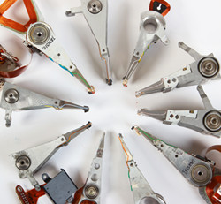
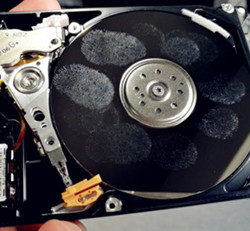
When we received damaged hard drives with stuck or jammed motors, we usually consider using some kind of hdd repair hardware to disassemble the hard drives, remove the heads carefully and then remove the platters of the patient drives to a donor hard drive. Well, this is not easy data recovery work especially when there're multiple platters of over 2 with dumpers between the platters.
We know there're some data recovery tools manufacturers claiming to be able to swap multiple platters with dumpers but few of them can do it with good result and even some of them caused second damage or permanent loss to our customers' data which disappointed and annoyed us a lot. There's one data recovery tools supplier declared their one-by-one platter exchange for jammed-motor drives with dumpers but it seems only their own clean room data recovery engineers are able to use that data recovery technology successfully but none of the rest. Maybe a thousand times' try will make it.
So what to do to increase our data recovery success rate while the traditional data recovery technology for jammed-motor drives failed?
Thanks to HDDsurgery, we got the spindle replacement tool. It's innovatively changing the way of clean room data recovery. It's to replace the jammed spindle instead of head and platter replacement which will be kept in place and alignment for successful data recovery. However, this tool is working so far for a limited drive families: Seagate 7200.11 and 7200.10 and support the following drive models: Read more here on data recovery magazine
Showing posts with label HDD repair tips. Show all posts
Showing posts with label HDD repair tips. Show all posts
Monday, January 30, 2012

Sunday, January 15, 2012
Look Into Chips on Hard Drive PCB
There're mainly four chips on a hard drive's PCB and this article will give you an general idea of where they are and what they do.
The first chip: The heart chip of one PCB
The heart of PCB is the biggest chip in the middle called Micro Controller Unit or MCU. On modern HDDs MCU usually consists of Central Processor Unit or CPU which makes all calculations and Read/Write channel - special unit which converts analog signals from heads into digital information during read process and encodes digital information into analog signals when drive needs to write. MCU also has IO ports to control everything on PCB and transmit data through SATA interface.

Chip 2: The Memory Chip
The Memory chip is DDR SDRAM memory type chip. Size of the memory defines size of the cache of HDD. Usually you find the size of memory in datasheet of the HDD, theoretically it means HDD has that size of cache but it's not quite true. Because memory logically divided on buffer or cache memory and firmware memory. CPU eats some memory to store some firmware modules and as far as we know only Hitachi/IBM drives show real cache size in data sheets for the other drives you can just guess how big is the real cache size.
Chip 3: VCM(Voice Coil Motor controller) controller chip
This chip is the most power consumption chip on PCB. It controls spindle motor rotation and heads movements. The core of VCM controller can stand working temperature of 100C/212F.
Chip 4: Flash ROM Chip
Flash ROM chip stores part of the drive's firmware. When you apply power on a drive, MCU chip reads content of the flash chip into the memory and starts the code. Without such code the drive wouldn't even spin up. Sometimes there is no flash chip on PCB that means content of the flash located inside MCU.
A million thanks to Data Recovery Salon for sharing such an excellent platform for sharing data recovery knowledge here. I will support you by sharing more of mine.
The first chip: The heart chip of one PCB
The heart of PCB is the biggest chip in the middle called Micro Controller Unit or MCU. On modern HDDs MCU usually consists of Central Processor Unit or CPU which makes all calculations and Read/Write channel - special unit which converts analog signals from heads into digital information during read process and encodes digital information into analog signals when drive needs to write. MCU also has IO ports to control everything on PCB and transmit data through SATA interface.
Chip 2: The Memory Chip
The Memory chip is DDR SDRAM memory type chip. Size of the memory defines size of the cache of HDD. Usually you find the size of memory in datasheet of the HDD, theoretically it means HDD has that size of cache but it's not quite true. Because memory logically divided on buffer or cache memory and firmware memory. CPU eats some memory to store some firmware modules and as far as we know only Hitachi/IBM drives show real cache size in data sheets for the other drives you can just guess how big is the real cache size.
Chip 3: VCM(Voice Coil Motor controller) controller chip
This chip is the most power consumption chip on PCB. It controls spindle motor rotation and heads movements. The core of VCM controller can stand working temperature of 100C/212F.
Chip 4: Flash ROM Chip
Flash ROM chip stores part of the drive's firmware. When you apply power on a drive, MCU chip reads content of the flash chip into the memory and starts the code. Without such code the drive wouldn't even spin up. Sometimes there is no flash chip on PCB that means content of the flash located inside MCU.
A million thanks to Data Recovery Salon for sharing such an excellent platform for sharing data recovery knowledge here. I will support you by sharing more of mine.
Subscribe to:
Posts (Atom)




 Posts
Posts

